Bridge Design and Assessment Spreadsheets
 These Design and Assessment Spreadsheets were written using Microsoft Excel 2000 and 2010 and they contain macros. Excel will need to be set to 'Enable Macros'.
Warning: The layout of the spreadsheet should not be changed. The macros carry out calculations using values from specific cells in the spreadsheet. If extra rows or columns are added the macro will still use the value in the old address and, as a result, will not give the correct answer.
Also OpenOffice should not be used to run these spreadsheets as the visual basic used in the macros does not translate directly into the OpenOffice.org Basic.
The spreadsheets are downloaded to you in a zip folder.

 DONATIONS
It is easy in today's climate, with COVID-19, to take for granted people's selfless, goodwill gestures. But all goodwill gestures can be a stepping stone to something more positive and life changing.
Therefore my small contribution towards furthering the access to, and understanding of, Bridge Design and Assessment to all Engineers is to make free all documents which had previously been for sale.
One charity which has worked tirelessly for many years in their contribution to cancer research supporting those affected by cancer is Macmillan Nurses. They have recently come into my life, for which I am grateful.
If you feel you benefit from using documents and information from this website, a donation towards Macmillan's Nurses will go a long way in helping this worthy charity.
Please use the link to donate to Macmillan Cancer Support. Thank you, David Childs.
Legal Stuff - Please Read.....[Show]
Disclaimer
These spreadsheets have been prepared to assist with the repetative design and assessment calculations for highway structures.
Users of these spreadsheets should verify for themselves the appropriateness of any values which they use for their own calculations and their own particular conditions, and should check for themselves the correctness of any results that they use.
David Childs has prepared these spreadsheets to assist designers, but he takes no responsibility for how the results are used.
Plane Frame Analysis for Static Loads
A Plane Frame Analysis for bending moments, axial and shears forces in a plane frame structure under point loads, UDL's, linearly varying distributed loads (soil pressures), moments, member elongation/contraction and end rotation.
Limits have been applied to the number of nodes (21), number of members (20), and number of loads in one load case (40).
Line Beam Analysis for Moving Vehicle Loads to BS 5400, BD 21 and BD 86
Abnormal Load Vehicles, HB Vehicles, BD21 Annex D Vehicles, the Standard Fatigue Vehicle and BD86 STGO Vehicles are analysed as moving loads across a single or multi-span continuous line beam to determine critical bending moments, maximum reactions and shear forces, with the facility to save the results. Abnormal load configurations may also stored in the workbook.
Analysis for Moving Vehicle Loads on Buried Concrete Box Structures to BD 31/01 & BS 5400
The standard HA KEL & UDL , Single HA Wheel, HB vehicles, Footway loading with Accidental wheel load, and Construction Vehicle Load Models are analysed as moving loads across a single or multi-cell box to determine critical bending moments, shear forces and axial forces using the matrix method of analysis for a 1m length of box.
Line Beam Analysis for Moving Vehicle Loads to Euro Code EN 1991-2:2003
The standard Tandem System with the UDL System (LM1), Annex A vehicles, SV's and SOV's to UK National Annex (LM3), and Fatigue Load Models are analysed as moving loads across a single or multi-span continuous line beam to determine critical bending moments, shear forces and reactions.
Analysis for Moving Vehicle Loads on Buried Concrete Box Structures to Euro Code EN 1991-2:2003 & PD 6694-1:2011
The standard Tandem & UDL System (LM1), Single Axle (LM2), SV's and SOV's to UK National Annex (LM3), Footway loading with UK Service vehicle and Accidental wheel load, and Construction Vehicle Load Models are analysed as moving loads across a single or multi-cell box to determine critical bending moments, shear forces and axial forces using the matrix method of analysis for a 1m length of box.
Line Beam Analysis for Static Loads and Settlement at Supports
A Line Beam Analysis for bending moments and shears forces in a single or multi-span continuous beam under point loads and UDL's. Settlement at supports may also be analysed.
Load Cases for Fixed and Free Abutments to BD30
Dead and Live load combinations are analysed for a fixed end or free end abutment. Stability and bearing pressure checks are carried out. Tables of moments and shears in the cantilever wall and base are also produced.
(Note: Not suitable for integral bridges.)
Load Cases for Fixed and Free Abutments to BS EN 1997-1:2004 & PD 6694-1:2011.
Seven permanent and variable load combinations are analysed for a fixed end or free end abutment. Normal traffic, SV/100 and SV/196 vehicles, or SOV vehicles can be analysed using the surcharge model described in PD 6694-1:2011. Stability and bearing pressure checks are carried out at SLS and ULS using Combinations 1 and 2 for Design Approach 1. Tables of moments and shears in the cantilever wall and base are also produced.
(Note: Not suitable for integral bridges.)
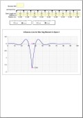
Influence Line Diagrams for single or multispan decks
Influence Line diagrams for bending moments at critical sections in a single or multi-span continuous beam.
Differential Temperature Effects to BS 5400-2:2006
Load effects due to vertical temperature differences through various types of bridge decks are analysed using non-linear effects as described in clause 5.4.5. Releasing moments and forces and self-equilibrating stresses are determined for the positive and reverse temperature differences.
Differential Temperature Effects to Euro Code EN 1991-1-5:2003 (& UK N.A.)
Load effects due to vertical temperature differences through various types of bridge decks are analysed using non-linear effects as described in clause 6.1.4.2. Releasing moments and forces and self-equilibrating stresses are determined for the heating and cooling temperature differences.
Temperature Effects on Box Culverts to Euro Code EN 1991-1-5:2003 (& UK N.A.)
Uniform temperature and temperature difference effects on single or multi-cell box culverts are analysed for structures with less than 1.5m of fill.
Self-equilibrating stresses are calculated together with releasing Forces and Moments. The spreadsheet then applies these Forces and Moments to the structure together with the uniform temperature effects. Simultaneity of uniform and temperature difference components are also calculated.
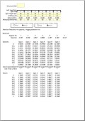
Distribution of Releasing Moments from Differential Temperature Effects on a Continuous Beam.
A line beam analysis is used to determine the secondary effects produced by the releasing moment from the differential temperature effects on a continuous beam using the moment distribution method.
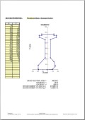
Section Properties of Solid Irregular Sections by Co-ordinate Geometry
Section properties, Area, Ixx, Iyy and xy co-ordinates of the centroid are determined for a solid irregular shaped section. Outline of the section is input using
x-y co-ordinates.
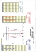
Section Properties of Voided Irregular Sections by Co-ordinate Geometry
Section properties, Area, Ixx, Iyy and xy co-ordinates of the centroid are determined for a voided irregular shaped section. Outline of the section and void is input using x-y co-ordinates. Circular voids can be input using the diameter and xy co-ordinates of their centre.
Prestressed Pretensioned Beam with composite insitu concrete deck slab to BS 5400 Pt. 4
The beam and deck are checked for the serviceability requirements of BS 5400 Part 4 for all stages of construction from transfer of prestressing force to long-term creep and shrinkage and live load effects.
Ultimate Limit State Moment Capacity of Prestressed Pretensioned Beams with composite insitu concrete deck slabs.
Spreadsheet (a) is to BS 5400 Pt. 4 for design to clause 6.3.3.1. and includes a check for ductility.
Spreadsheet (b) is to BD 44/15 for assessment of beams with bonded prestressing tendons to clause 6.3.3.1. and allows for a ductility check to be carried out.
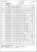
Bar Schedule to BS 8666:2005
Calculates bar lengths for standard bar shapes and produces summaries of lengths and weights for bar types and diameters. Includes checks for compliance with the code requirements.
Serviceability Limit State & Early Thermal Cracking Checks to BS 5400 Pt. 4 & BD 28/87
Solid rectangular reinforced concrete sections are checked for the serviceability requirements of BS 5400 Part 4 for complying with crack width requirements to Clause 5.8.8.2 and stress limitations to Clause 4.1.1.3.
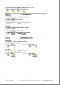
Wood & Armer equations for plate bending design and assessment calculations.
Wood & Armer analysis to optimise steel reinforcement to resist Mx, My and Mxy plate bending moments. Also analyses M*y reinforcement requirements for M*x provided.
Reinforced Concrete Slab Design to BS 5400 Pt. 4 Clauses 4.1.1.3, 5.3.2.3 (eqn. 1 & 2), 5.4.4.1 & 5.8.8.2.
Bending moment capacities for ultimate limit and serviceability limit states together with shear capacity for a range of slab thicknesses and bar diameters.
Useful for determining suitable steel arrangements quickly. A calculation sheet is automatically prepared for the desired reinforcement layout.
Reinforced Concrete Slab Design to Eurocodes EN 1992-2:2005 & UK National Annex
Bending moment capacities for ultimate limit and serviceability limit states together with shear capacity for a range of slab (or wall) thicknesses and bar diameters. Useful for determining suitable steel arrangements quickly. A calculation sheet is automatically prepared for the desired reinforcement layout.
General Reinforced Concrete Section Design to Eurocodes EN 1992-2:2005 & UK National Annex
Bending moment capacity at ultimate limit state, serviceability limit state checks and shear capacity calculations for a general reinforced concrete section. Both tension and compression reinforcement can be included in a section of varying widths symmetrical about the vertical axis. Efficient stirrup arrangements can be obtained by an interacive analysis.
Early Age Thermal Crack Control to Eurocodes EN 1992-3:2006 & UK National Annex applicable to bridges, incorporating CIRIA Report C660 recommendations.
Calculates the area of steel reinforcement required to control early age thermal cracking using methods described in CIRIA Report C660 "Early Age Thermal Crack Control in Concrete".
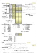
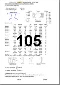
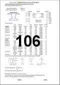
Riveted Plate Girder Section Properties
Section properties of a riveted plate girder to
BD 56/10 and BS5400-3:2000 with facility to allow for corroded elements. The slenderness parameter λLT and limiting moment of resistance MR are also determined.
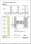
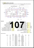
Effective Span of Plate Girder with no Bearing
The effective span and maximum bearing pressure for a plate girder with no specific bearing is calculated in accordance with BD 56/10 clause 16 and Figure 16.1A
Filler Beam Yield Moment & Plastic Moment Capacities to BD 61/10
Two spreadsheets for determining the moment capacities of filler beam sections in accordance with BD 61/10. Checks are carried out on the bond between the steel and concrete at serviceability and ultimate limit states.
Section Properties of Composite Bridge Beams to BS 5400 Pt.3:2000 & Pt.5:2005
Two spreadsheets for determining the elastic and plastic section properties of a composite beam comprising a steel plate girder with unstiffened flanges and a reinforced concrete deck for internal and edge beams. The concrete deck may be analysed in tension or in compression. Shear lag calculations are included for SLS properties. Compact Section checks are carried out and the appropriate Plastic Moment of Resistance or Permissible Ultimate Elastic stresses are calculated.
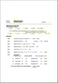
MEXE analysis to BD 21/01.
The modified MEXE analysis to BD 21/01 and BA 16/97 for single span masonry arch with option for axle lift-off.
Axle lift-off criteria for hump back bridges.
An assessment of the road profile to determine if axle lift-off may occur for application with the MEXE analysis.

